Physical modelling
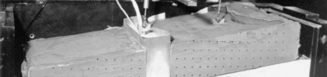
Physical modelling is what most defines us. We reproduce phenomena and apply loads directly on a model of an existing or planned structure, to study soil structure interaction under static and seismic conditions without relying on a priori assumptions.
Typical applications
- Shallow and deep foundations
- Tunnels
- Retaining walls
- Dams
- Levees and embankments
- Seismic phenomena
- Liquefaction
- Landslides and slope stability
Why a physical model
- It reproduces extreme loading in a controlled environment, up to failure and beyond.
- Tests can be repeated to run parametric analyses.
- Time and cost are lower than for real-scale testing.
- It complements numerical modelling: it calibrates parameters and constitutive laws and checks the assumptions about the phenomena studied.
Calibration chamber
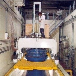
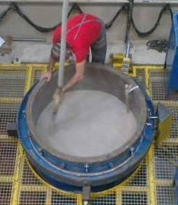
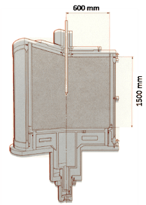
The calibration chamber reproduces in the laboratory, at 1:1 scale, the in-situ effective stress state of a soil volume. It is a large cylindrical chamber in which the sample is reconstituted to the required grading and density, then consolidated to the stress state of the site at the depth of interest.
The chamber applies independent lateral and vertical confinement, so it can reproduce isotropic or anisotropic stress states. Inside it we run penetrometer, dilatometer and pressuremeter tests with the same equipment and procedures used on site.
- Diameter
- 120 cm
- Height
- 150 cm
- Tests replicated
- CPT, CPTU, DMT, SBPM, CH, DH, PLT
- Validating and calibrating interpretation models.
- Defining correlations between reconstituted soil parameters and test results.
- Developing, checking and calibrating testing tools.
Large direct shear and pull-out
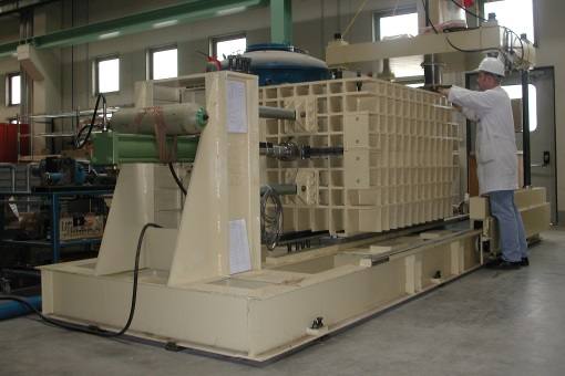
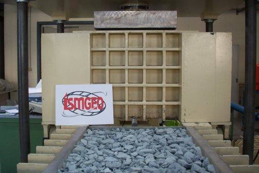
A large and very versatile shear box that holds reconstituted soil specimens tested under K0 stress conditions.
- Direct shear
- 70 × 70 × 70 cm
- Pull-out
- 140 × 70 × 100 cm
- Maximum particle size
- 12 cm
- Mechanical characterisation of gravels and coarse soils.
- Soil structure interface behaviour: geomaterials, micropiles, walls.
- Qualification of reinforcements and rigid or deformable inclusions, with geomaterials up to 70 × 140 cm.
Real-scale models
We build instrumented real-scale models of structures. Some examples:
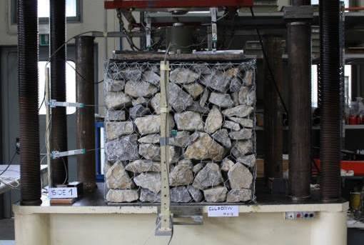
Gabion walls
Gabions under vertical load, in confined and unconfined conditions, to measure their deformability and strength.
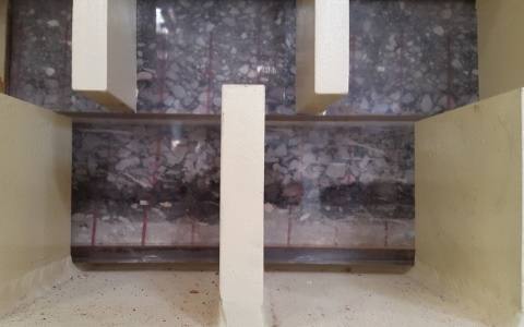
Bitumen rockfill interface for BFRD dams
Large shear box tests on the interface between rockfill and bituminous facing for the Nenskra dam in Georgia.
Reinforced soil structure
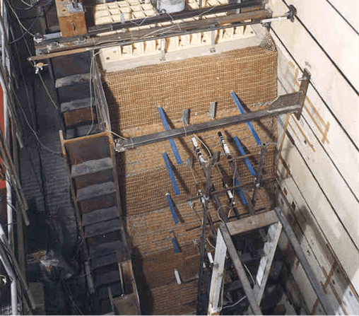
A real-scale wall (h 3.8 m, d 5.11 m, w 2.13 m) with a 70° facing, built in compacted sand layers reinforced with steel grids and geogrids. Reinforcements instrumented with strain gauges, displacement transducers and load cells, loaded at the top until collapse.
Fatigue of reinforced asphalt
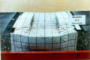
A reinforced road pavement section under cyclic loads simulating traffic: the steel reinforcement reduces settlement and delays cracking.
A structure to verify?
Tell us about the ground, the structure and your timing: we will propose the right testing programme.